rbritton1201
Captain1201
- Joined
- Jul 27, 2020
- Messages
- 407
- Reaction score
- 81
I have a Comet H-422 Rotatable Dipole Antenna for use on the 10-40 meter HF amateur radio bands, and I want to install a new DPD Productions "Omni-X" Scanner Antenna mast/antenna on that portion of the Dipole's mast that extends a little beyond where the base of the Comet H-422 Rotatable Dipole base is installed on its mast.
Since the "V" shape of the rotatable dipole is pretty wide as is, I figure that the Omni-X elements should be about 2.5' to 3', or more, from the elements of the rotatable dipole once the Omni-X's mast is clamped onto the extension of the rotatable dipole's mast. I can also extend the length of the end of the rotatable dipole mast further up to create an even a greater distance for the Omni-X elements from the "V" elements of the dipole if necessary. But, I don't know if it would even be necessary with the frequency separation that exists between VHF/UHF/225-900 Mhz. and the HF 10-40 meter bands.
Installation of the DPD Productions "Omni-X" antenna is via a couple of plastic clamps provided so that the manufacturer supplied pre-assembled scanner antenna/mast assembly can be mounted to an aluminum mast.
I am hoping that by affixing the DPD Productions "Omni-X" scanner antenna mast to the aluminum mast that extends up from the rotatable dipole's mount, it won't create RF coupling situation, or that the Dipole elements will block reception via the Omni-X scanner antenna. My calculations say that provided there is at least 1.7 feet of separation from the Dipole elements, there should not technically be any RF coupling occurring.
As an added precaution, I always turn off receivers that may be in close proximity to other antennas when transmitting with my HF, VHF/UHF ham equipment, just to avoid any damage to the scanners that may potentially occur were I to leave the scanner on while transmitting. The Dipole is designed to be rotatable, but I have it stationary, and I'm not intending to use a rotator.
Using the existing mast extension above the rotatable dipole is ideal with respect to grounding that already exists for the Dipole antenna, which is grounded at the base with an 8' copper pipe, then "bonded" to the service ground via #6 solid copper wire. I plan to also install a lightning arrestor at the base of the Dipole's mast to bleed off transients that might build up with respect to the Omni-X antenna. To reiterate, the ground rod at the base of the Dipole is also bonded to the service ground via #6 solid wire.

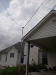
Comet H-422 Rotatable Dipole Antenna for 10-40 meters, HF transmit and receive.

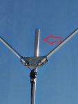
Aluminum mast extension above the base mounting of the Comet H-422 Rotatable Dipole Antenna (see red arrow).

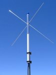
DPD Productions Omni-X Scanner Antenna
Gain: 3 VHF 4 UHF dBi
Pattern: Omni-directional
Wavelength: 1/2
Elements: 3
Tuned: 118-137, 148-175 & 225-900 MHz
Band: UHF & VHF
Connector: N Female
Cable: RG8X
Cable Length: 16 Inches
Height: 45"
Width: 30"
Weight: 2 lb
Multi Band-Wide Coverage: The uniquely designed OmniX is tuned to multiple bands, giving it wide frequency coverage. Unlike antennas that were originally designed for the ham bands and then marketed as a scanner antenna, the OmniX was specifically designed for scanner radio use and tuned to popular commercial and civil service bands. Elements are specifically tuned for 118-137 MHz, 148-175 MHz and 225-900 MHz, but other bands can be received as well. This antenna can be quite aesthetically pleasing compared to discones and it's also more efficient.
DC Grounded: A metal ground plane is not needed with this design.
Solid Construction: The antenna is constructed of 1 1/2" aluminum tube for the core element and solid 1/4" aluminum round is used for side elements. No flimsy tubing or dimple rivets are used. All aluminum is given a brushed finish.
Isolated Mast: The actual vertical structure is comprised of UV resistant plastic. This allows the actual elements to be raised into 'free space', away from your metal mounting mast.
Weather Resistant: All fasteners are stainless steel and the feed point is protected by shrink tube.
High Quality N Connector: Instead of the usual UHF connector that's included with most antennas, this antenna includes a 50 ohm female N connector, on the end of a small cable pigtail. N connectors are more water resistant and handle high frequencies better. Need help choosing your main cable? Checkout the Coax FAQ.
Includes Mounting Hardware: Price includes mounting clamps to allow attaching the antenna to any standard 1 1/4" to 1 1/2" mounting mast.
Only Partial Assembly Required: The core antenna is completely assembled, along with the feeder cable. The only things that need to be done yourself are attaching the side elements, and putting up a mast.
Since the "V" shape of the rotatable dipole is pretty wide as is, I figure that the Omni-X elements should be about 2.5' to 3', or more, from the elements of the rotatable dipole once the Omni-X's mast is clamped onto the extension of the rotatable dipole's mast. I can also extend the length of the end of the rotatable dipole mast further up to create an even a greater distance for the Omni-X elements from the "V" elements of the dipole if necessary. But, I don't know if it would even be necessary with the frequency separation that exists between VHF/UHF/225-900 Mhz. and the HF 10-40 meter bands.
Installation of the DPD Productions "Omni-X" antenna is via a couple of plastic clamps provided so that the manufacturer supplied pre-assembled scanner antenna/mast assembly can be mounted to an aluminum mast.
I am hoping that by affixing the DPD Productions "Omni-X" scanner antenna mast to the aluminum mast that extends up from the rotatable dipole's mount, it won't create RF coupling situation, or that the Dipole elements will block reception via the Omni-X scanner antenna. My calculations say that provided there is at least 1.7 feet of separation from the Dipole elements, there should not technically be any RF coupling occurring.
As an added precaution, I always turn off receivers that may be in close proximity to other antennas when transmitting with my HF, VHF/UHF ham equipment, just to avoid any damage to the scanners that may potentially occur were I to leave the scanner on while transmitting. The Dipole is designed to be rotatable, but I have it stationary, and I'm not intending to use a rotator.
Using the existing mast extension above the rotatable dipole is ideal with respect to grounding that already exists for the Dipole antenna, which is grounded at the base with an 8' copper pipe, then "bonded" to the service ground via #6 solid copper wire. I plan to also install a lightning arrestor at the base of the Dipole's mast to bleed off transients that might build up with respect to the Omni-X antenna. To reiterate, the ground rod at the base of the Dipole is also bonded to the service ground via #6 solid wire.

Comet H-422 Rotatable Dipole Antenna for 10-40 meters, HF transmit and receive.

Aluminum mast extension above the base mounting of the Comet H-422 Rotatable Dipole Antenna (see red arrow).

DPD Productions Omni-X Scanner Antenna
Gain: 3 VHF 4 UHF dBi
Pattern: Omni-directional
Wavelength: 1/2
Elements: 3
Tuned: 118-137, 148-175 & 225-900 MHz
Band: UHF & VHF
Connector: N Female
Cable: RG8X
Cable Length: 16 Inches
Height: 45"
Width: 30"
Weight: 2 lb
Multi Band-Wide Coverage: The uniquely designed OmniX is tuned to multiple bands, giving it wide frequency coverage. Unlike antennas that were originally designed for the ham bands and then marketed as a scanner antenna, the OmniX was specifically designed for scanner radio use and tuned to popular commercial and civil service bands. Elements are specifically tuned for 118-137 MHz, 148-175 MHz and 225-900 MHz, but other bands can be received as well. This antenna can be quite aesthetically pleasing compared to discones and it's also more efficient.
DC Grounded: A metal ground plane is not needed with this design.
Solid Construction: The antenna is constructed of 1 1/2" aluminum tube for the core element and solid 1/4" aluminum round is used for side elements. No flimsy tubing or dimple rivets are used. All aluminum is given a brushed finish.
Isolated Mast: The actual vertical structure is comprised of UV resistant plastic. This allows the actual elements to be raised into 'free space', away from your metal mounting mast.
Weather Resistant: All fasteners are stainless steel and the feed point is protected by shrink tube.
High Quality N Connector: Instead of the usual UHF connector that's included with most antennas, this antenna includes a 50 ohm female N connector, on the end of a small cable pigtail. N connectors are more water resistant and handle high frequencies better. Need help choosing your main cable? Checkout the Coax FAQ.
Includes Mounting Hardware: Price includes mounting clamps to allow attaching the antenna to any standard 1 1/4" to 1 1/2" mounting mast.
Only Partial Assembly Required: The core antenna is completely assembled, along with the feeder cable. The only things that need to be done yourself are attaching the side elements, and putting up a mast.
Last edited:

