would you please post a list of parts and numbers. I'd like to give this a shot. I don't want to cut the case, so a bit tricky to make it work.
You can't do the mod without cutting the case. The GPS module will not physically fit in the available space inside the 436 without the cutout. And all the other GPS modules I've tried (over a dozen) cause some degree of RFI trouble.
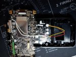
I use a drill press with an X-Y table and digital position readouts for the X, Y, and Z axes to make the cutout. This enables me to precisely locate and size the cutout for the patch antenna and the holes for the LED indicators in the rear case, so that the GPS module fits in the cutout properly, the status LEDs align properly with their holes, and the module doesn't short against any of the other components in the scanner. I use a 1/4-inch diameter 2-flute end mill for the antenna cutout (that's how I get the corners of the cutout rounded to match the contour of the patch antenna), and a 3/32" drill for the rear LED holes.
The rest of the process is more straightforward, and can be replicated by anyone with decent soldering skills and basic hand tools.
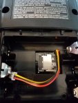
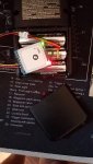
The GPS connector is a 6-pin JST 1.25mm, and the LED connector can be a 2 or 3-pin JST 1.25mm. The power switch connectors are 2-pin JST 2.0mm female connectors with the tips cut off as shown in the 4th photo (I have to trim the switch pins to allow the rear circuit board to fit in place, so part of the connector must be cut off for the connector to engage the pins). The The RFI suppression toroid has a 6mm OD, 3mm ID, and is 2mm thick.
The power switch is a 5.8mm latching DPDT pushbutton with 2mm pin spacing.
The front panel status LED is a standard clear 3mm LED, which I grind flat so that is sits flush with the front case, and has a frosted finish so the light shines more uniformly in all directions). I choose resistor values to keep the LED current around 1mA, which makes it bright enough to see in daylight without causing excessive battery drain.
I use Liquid Nails to glue the power switch in place, and clear DAP window caulking (not silicone based) to glue the GPS module and the front panel LED in place. That allows the rear LEDs on the GPS modules to be visible--I let it fill the holes and act as a light pipe.