https://1drv.ms/f/s!ApJIS-l4xqPtgu9sYWN21iXx9-H1WA
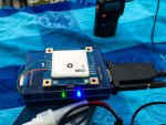
An updated photo gallery showing the GPS install process in a HP-2.
An updated photo gallery showing the GPS install process in a HP-2.

Jon,I've run across a possible issue with the default configuration of the RYN25DI modules. The default configuration setting for position fix output is Auto 2D/3D, but instead of reverting to a 2D fix when there aren't enough satellites to calculate a 3D fix, the module doesn't output any fix at all. So in that situation, the indicator LED will say the unit has a fix, but the fix isn't being output.
The solution seems to be to go to the NAV5 section in the U-Center configuration utility, and change the Dynamic Model to Automotive, and the Fix Mode setting to 2D Only. The module will only output 2-D fixes (no altitude), but will do so whenever the indicator LED shows a satellite lock. The calculated position is less precise, (95% within a 100-meter circle instead of 95% within a 10-meter circle), but you at least get get something even when reception is poor.
ThanksIf you have the Uniden factory GPS cable, plug the cable into the GPS port on the scanner and the DB9 end into a RS232 serial adapter. When the internal GPS is running you will be able to see the serial data sent from the GPS to the scanner.
Using the u-blox utility, watch the GPS status when it cold starts, and see if there is a time interval between the status light starting to blink and th No Fix indicator in the utility changing to 2D or 3D. If the GPS is showing green signal reception from 3 or more satellites and No Fix for more than a second or two, then you have the issue. Reconfiguring the module to 2D fix only forces it to output a fix even if it doesn't have enough signals to calculate a 3D fix.
https://www.u-blox.com/en/product/u-center-windows
This is the download page for the GPS utility.
Quick question. Is this pinout good for the 996p2 also? I have a GPS puck I would like to power from the scanner, but it needs 5v on pin 4. I don't want to let any of the magic smoke out of my scanner trying to hook it all up ;-)

I finally worked up the guts to try this. Since my 996p2 is out of the truck while I figure out where to put in in the new truck.
Breaking 5v to pin 4 worked fine. No ill effects to the scanner, and the GPS puck I have works fine. I'm using a Byonics GPS-2 (no longer available) that I purchased for APRS.. Works great for the scanner and I didn't have to modify the GPS plug.
As long as pin 4 wasn't connected to anything else in the scanner, you're good. I assume you checked for voltages and connection to ground first.
I've just finished some torture testing on this GPS/GLONASS module:
RY636AI USB/UART interface High Performance GPS antenna module | eBay
But the reception it gets is INSANE. Cold boot in the house after opening the package from China took about 15 seconds to get a fix. I have been unable to get it to lose satellite fix in any test I've done so far. This test breaks satellite lock on every other GPS receiver I've tested, but not this beast.
Did you need to convert from TTL to RS232? If so, what chip/converter did you use?
The RYN25DI is nice because it does not need a converter. Are there any other modules that output rs-232 that do not need a converter? I have a trip is 2 weeks away and anything from over seas will take to long.