
Internal GPS Mod Tech Support/Q&A
- Thread starter jonwienke
- Start date
- Status
- Not open for further replies.
Strange though that it works ok with external sources.
True, but the only way to figure out the difference is to look at the signals with an o-scope. Signal levels may be high enough to trigger your logic analyzer, but not the on-board UART. Measure the actual signalling voltages at each step of the process:
TTL output from the GPS.
RS-232 output from the MAX3232 or Uniden puck.
TTL and STATUS outputs from the scanner's on-board UART.
Compare your readings between running the ATGM336H and the Uniden GPS. If the Uniden GPS works, and the ATGM336H doesn't, you should be able to spot the difference. One of the voltage levels will be different.
So after some extensive testing, Mancow and I have determined that the ATGM336H will NOT work as a GPS for Uniden scanners, because it does not send the NMEA sentences that the scanners are looking for. Back to the drawing board...
436 & 536 mods done
I've recently had the GPS mods done to both my 436 and & 536 scanners and I couldn't be happier. I've had no issues whatsoever on either scanner since modification. If you're like me, I can't stand those cords everywhere while using an external GPS. Now the puck is always connected by by 1 single cord to the 536, and unless I turn it off, it's on the majority of time on the 436 as well. I haven't seen any issues with battery consumption on the 436 whatsoever, sure it does use power from the batteries but it hasn't been even noticeable!
Thanks for the great work Jon!
Robert
You're welcome.
On my modded 436, GPS on gives me about 7-1/2 hours of battery life, vs a bit over 8 with GPS off. YMMV depending on batteries, screen settings, volume level, activity levels, etc. It does make a difference, but you're probably not going to notice it unless you consult a stopwatch.
On my modded 436, GPS on gives me about 7-1/2 hours of battery life, vs a bit over 8 with GPS off. YMMV depending on batteries, screen settings, volume level, activity levels, etc. It does make a difference, but you're probably not going to notice it unless you consult a stopwatch.
Of course, that requires that 5V power be supplied to the DB-9 connector. Conveniently, there is a 5V pad on the circuit board not too far from the DB-9 connector. I connected power to pin 9, which is traditionally used for the ring indicator, and is not connected to anything in the Uniden GPS cable assembly.
The pinout on the female DB-9 connector is as follows:
1 NC
2 Scanner data RX (serial data from GPS to scanner) - Green wire
3 Scanner data TX (serial data from scanner to GPS) - White wire
4 NC
5 Ground - Black wire and shield
6 NC
7 NC
8 NC
9 +5V (power tapped from scanner) - Red wire
Quick question. Is this pinout good for the 996p2 also? I have a GPS puck I would like to power from the scanner, but it needs 5v on pin 4. I don't want to let any of the magic smoke out of my scanner trying to hook it all up ;-)
The pinout I gave is the standard DB-9 RS232, except that the ring indicator on pin 9 has been replaced with +5V. I've tested it with the 996P2 and the 536HP. I picked pin 9 because it seemed the least likely candidate for interference or compatibility problems.
Is there any possibility you could move the +5V lead from pin 4 to pin 9 on your puck?
Is there any possibility you could move the +5V lead from pin 4 to pin 9 on your puck?
I'd have to hack the end off. And I have 2 of these, one feeding my D-710 (And split to the 996p2) and I'd like to give the 996p2 it's own GPS. I'd hate to modify it and it not be interchangeable in the future..
I haven't had anyone interested in having me mod one yet. But I know it is doable, others have successfully installed the Ladybird GPS in a HP-2. I'd have to take one apart to be sure, but I believe that a Reyax module could be installed, if one was willing to make a cutout for the GPS patch antenna.
Been reading through this post, awesome work! I've got two BCT15Xs and a 996P2 with just the one Uniden GPS at the moment. The 15Xs are mobile and one has the GPS on it..well, 'had', its now not working now lol. I like the reports for the RY636AI USB/UART GPS, I'm thinking about mounting it internally in all 3 of my scanners. Do you think there will be any issues mounting them inside the case? I know its not ideal, but I'd love to have a clean look. Both 15Xs are in dodge 3500 trucks and are mounted either in the dash or hung from a console on the ceiling. The 996P2 is the base station, and that GPS could be externally mounted if needed.
Mounting internally on the 996 or any other mobile scanner is a no-go, because the case is metal and will effectively block the signal from reaching the antenna. You need to mount a 636 module to the top of the scanner (as shown in post #32, which also allows you to see the indicator lights) or else mod the scanner and Uniden puck to connect directly.
Last edited:
Well, that both sucks and makes sense. I'm not willing to modify the external of my cases yet, so it looks like the cable/puck mod.
The cable/puck you offer, does that require any internal modifications like the 5v power tap? I still like the RY636AI GPS unit, so I may make a cable for that and use them instead of the GlobalSat BR-355S4 GPS.
The cable/puck you offer, does that require any internal modifications like the 5v power tap? I still like the RY636AI GPS unit, so I may make a cable for that and use them instead of the GlobalSat BR-355S4 GPS.
Part of the mod is connecting +5V to pin 9 inside the scanner. Otherwise you have to have extra wiring to power the puck.
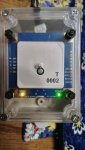
If you want to connect the 636 externally, you will need to fabricate a case to put it in, preferably with a transparent top so you can see the onboard indicator lights, and will also need a MAX3232 adapter to convert the output to RS232.
I have the tooling to make the case cutout with straight smooth edges, properly centered around the GPS, if that makes any difference.
If you are going external, I would go with the BR-355S4 over the Reyax. Having the GPS on a cord means you're going to get a signal even if it isn't the absolute best performing unit.
Just curious, is there any chance of over amping the GPS with this 5v tap mod? I dont plan on jamming paperclips in my serial port lol, so I dont think it'll be an issue. I might put a diode on it just to prevent any weird mishaps or reverse voltage (literally never going to happen).
You recommended using pin 9 for the 5V line. Will this be an issue if I use the serial port plugged into my computer? (cant remember if you covered that already). I'd assume not.
And I still might use the RY636, I just like it") Plus the added function of the diagnostic port and the software to view its functions, its just cool.
Plus the added function of the diagnostic port and the software to view its functions, its just cool.
Post #9
If you made a case and cable for the RY636, I might be interested I know its reinventing the wheel, but this would be a much cooler wheel.
You recommended using pin 9 for the 5V line. Will this be an issue if I use the serial port plugged into my computer? (cant remember if you covered that already). I'd assume not.
And I still might use the RY636, I just like it
Plus the added function of the diagnostic port and the software to view its functions, its just cool.Post #9
I have some DB-9 shells on order, when they come in, I will see if the MAX3232 module could fit inside.
If you made a case and cable for the RY636, I might be interested
I know its reinventing the wheel, but this would be a much cooler wheel.
Last edited:
No. You only get an overcurrent condition if you have a short circuit or increase voltage significantly above 5V.
If you connect the puck's power lead to pin 9 of the DB9, it won't power up unless the DB9 port you plug it into is also modded with 5V on pin 9. Unless you mod your computer, plugging the GPS into your computer will do nothing.
Putting the RY636 and a MAX3232 in a clear case is doable, it just ends up costing more than the BR-355S4 once you figure in the fabrication time and effort. It looks cooler, though.
- Status
- Not open for further replies.
Similar threads
- Replies
- 15
- Views
- 622
BCD436HP/BCD536HP:
Uniden UBCD436-PT not holding Favouites
- Replies
- 10
- Views
- 424
BCD325P2/BCD996P2:
A BCD996P2 in my future... What do I need to buy?
- Replies
- 21
- Views
- 1K