• To anyone looking to acquire commercial radio programming software:

    Please do not make requests for copies of radio programming software which is sold (or was sold) by the manufacturer for any monetary value. All requests will be deleted and a forum infraction issued. Making a request such as this is attempting to engage in software piracy and this forum cannot be involved or associated with this activity. The same goes for any private transaction via Private Message. Even if you attempt to engage in this activity in PM's we will still enforce the forum rules. Your PM's are not private and the administration has the right to read them if there's a hint to criminal activity.

    If you are having trouble legally obtaining software please state so. We do not want any hurt feelings when your vague post is mistaken for a free request. It is YOUR responsibility to properly word your request.

    To obtain Motorola software see the Sticky in the Motorola forum.

    The various other vendors often permit their dealers to sell the software online (i.e., Kenwood). Please use Google or some other search engine to find a dealer that sells the software. Typically each series or individual radio requires its own software package. Often the Kenwood software is less than $100 so don't be a cheapskate; just purchase it.

    For M/A Com/Harris/GE, etc: there are two software packages that program all current and past radios. One package is for conventional programming and the other for trunked programming. The trunked package is in upwards of $2,500. The conventional package is more reasonable though is still several hundred dollars. The benefit is you do not need multiple versions for each radio (unlike Motorola).

    This is a large and very visible forum. We cannot jeopardize the ability to provide the RadioReference services by allowing this activity to occur. Please respect this.

Programming a Minitor Pager on the Cheap - DIY Style Write Up

Status
Not open for further replies.

krokus

Member
Premium Subscriber
Joined
Jun 9, 2006
Messages
6,128
Location
Southeastern Michigan
Wirelessly posted (Opera/9.80 (Android 2.3.4; Linux; Opera Mobi/ADR-1309251116) Presto/2.11.355 Version/12.10)

WX9EMS said:
Why would you tear apart an amplified base to make a programming base? Seems like a waste, but I guess use what you have. I made mine out of two charging bases I acquired on the cheap. I added the missing pin/spring from the other charging base, and modified the pcb. Added a RJ-45 jack into the rear of the base. The programming base has been wired to work with a Kenwood KPG-46 programming cable.

In my case, I had two that were broken, and were free.

My agency moved to a different brand of pager, for our house bells, due to the lack of reliability of the V's amp base.
 

FFKingsford

Member
Joined
Jun 12, 2008
Messages
17
Success!

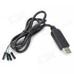
I just made a pager programmer using a Minitor V Charger, a PL2303HX USB Cable I found on eBay for $4, some pins off of an old logic board (LB) out of a computer, hot glue and some solder!

I soldered the pins from the LB at a 90 degree angle onto the pins from the rear battery charger (because they are longer. I then placed the pins from the battery in the 4 pin holes for the programming mode. I put the pager in the charger (to get the appropriate depth for the pins to make contact) and hot glues them into place. Connected the cables from the USB PL2303HX I bought. Closed up the bottom and BAM! $4 pager programmer.
 

xcrownvicx

Newbie
Premium Subscriber
Joined
Jun 16, 2014
Messages
5
Location
New Jersey
Hi would this work USB To RS232/TTL PL2303HX Cable COM on eBay and then just cut the ends of the wires and put pins. Thanks.
 

SB-Wi

Member
Premium Subscriber
Joined
Jun 20, 2011
Messages
297
Location
Eastern Dane Co
Download Fails

I think I've tried reading a Minitor IV every which way but it fails after 7 of 10 bars. I've tried the WinXP computer serial port and Belkin USB PDA adapter with muliple settings for the COM port. The Belkin shows a solid light on RX when reading so I think I have the correct pinouts (2 3 & 5) on the F-F cable. I downloaded the Minitor IV PPS v2.1.0 direct from Motorola through my online account. The pager is in programming mode (C selection and hold reset until tone stops). Both lights on the pager remain off while reading. It seems like the download gets interrupted and shows a failed connection. Any suggestions?
 

jonnyvee

Newbie
Joined
Dec 4, 2014
Messages
1
V

I just made one of these, used a dead charger and removed the board, I then used clear plastic of the same thickness as the board and cut it to size, moved the charger pins and springs to the right holes and had holes drilled in the plastic at those spots, used the usb cable with about 1/4" wire showing and stuck in the hole and taped with a quarter on top, put the bottom on and it works great, pretty crude but looks good and the pins are still spring loaded. will try and post a pic soon. saved my local a few bucks for some thing they can use better. Thanks guys.
 

SCPD

QRT
Joined
Feb 24, 2001
Messages
0
Location
Virginia
Minitor 4 Programmer Issue

I made a vary generic form of a charger, I did it this way to ensure that I was doing it properly, before I dismantle my charger & make it a charger/programmer. I looked thru a lot of the messages & pictures to understand what i needed to do. I will explain what i did & explain whats not working, then if anyone can help me understand what I doing wrong or needs pics of what i have done, i will take & post them. Please, be understanding & don't beat me up to hard with my prototype of my programmer(lol), thanks..... I had a usb cord that i took & cut off one end of the cord, leaving me with a usb plug & several feet of wire attached at the other end. Secondly, I got pinout diagrams for the programming mode for the Min 4 & I got pinout diagram for my usb connecter, after researching i had found the correct wires to connect to the correct locations on the bottom of the pager. 3rd, I took the idea from a posting I saw, I used a 2x4, with the house electrical wiring to use as pins to connect to bottom of the pager, to communicate. So now I am wired up properly, I connect the pager to my protype/homemade charger, I connect the usb to my comp usb connector. I turn on my program, but don't have communication with my pager. I do not know if I need a driver installed in my computer because i'm using a usb. I'm using windows 8.1 & I have the correct minitor 4 program software downloaded. If any one can help me with some advice or guidance, I would be super appreciative. I just wanted to make sure I was doing all my wiring & everything correct, before I dismantle & buy the few supplies I would need to make a better quality programmer. I am not a big computer technical person, but i am vary proficient with automobile electrical diagnostics, so I have some knowledge of things, just not much computer knowledge. Thanks So Much...GEORGE
 

SCPD

QRT
Joined
Feb 24, 2001
Messages
0
Location
Virginia
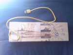
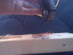
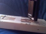
Pics of my Programmer

As I posted in my message above, These are some pics of my programmer, hoping this might help someone understand what i'm doing/not doing correct. This idea of using a 2x4 came from Radioetceetra , Min programmer Site. Thanks for The Help.
 

Attachments

  • IMG_20150128_130153_495.jpg
    IMG_20150128_130153_495.jpg
    43.5 KB · Views: 1,350
  • IMG_20150128_130250_200.jpg
    IMG_20150128_130250_200.jpg
    45 KB · Views: 1,174
  • IMG_20150128_130331_996.jpg
    IMG_20150128_130331_996.jpg
    43 KB · Views: 1,586

SteveC0625

Order of the Golden Dino since 1972
Joined
Oct 24, 2009
Messages
2,797
Location
Northville, NY (Fulton County)
Go back and read the entire thread. You missed the part about using a USB to serial cable that has the TTL and other circuitry built in. You can not use just a plain USB cable.
 

SCPD

QRT
Joined
Feb 24, 2001
Messages
0
Location
Virginia
TTL USB Converter

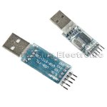
OK, I did read that, I miss understood what that was saying. I thought I only need a TTL converter if I needed to supply power to the pager to program it(I thought I could the batteries in the pager for that). So that i totally understand, I need a USB cable that has a TTL converter in it. This is why I was making a cheap prototype, before I messed up a good charger or bought parts that were not needed or screwed them up as well. I see at the top of this page for this thread, someone(FFKingsford) bought & used a PL2303HX, I went on ebay & I see "USB To RS232 TTL PL2303HX Auto Converter Module Converter Adapter For arduino", is this what I would need to complete my cable?? I'm Sorry for these amateur & probably stupid questions everyone, I just don't like to make something, I would prefer to learn about what i'm making. So if this "PL2303HX" is what i'm missing or need, I would plug that into my USB port & connect the wires to my programmer, using a wiring diagram?? THANK YOU VARY MUCH FOR THE HELP & KNOWLEDGE.
I posted a second picture showing the same PL2303HX with a length of wire attached to it....THANKS AGAIN.
 

Attachments

  • PL2303HX Image-001.JPG
    PL2303HX Image-001.JPG
    42.8 KB · Views: 1,251
  • USB TTL CONV.JPG
    USB TTL CONV.JPG
    20.6 KB · Views: 1,388
Last edited:

SteveC0625

Order of the Golden Dino since 1972
Joined
Oct 24, 2009
Messages
2,797
Location
Northville, NY (Fulton County)
OK, I did read that, I miss understood what that was saying. I thought I only need a TTL converter if I needed to supply power to the pager to program it(I thought I could the batteries in the pager for that). So that i totally understand, I need a USB cable that has a TTL converter in it. This is why I was making a cheap prototype, before I messed up a good charger or bought parts that were not needed or screwed them up as well. I see at the top of this page for this thread, someone(FFKingsford) bought & used a PL2303HX, I went on ebay & I see "USB To RS232 TTL PL2303HX Auto Converter Module Converter Adapter For arduino", is this what I would need to complete my cable?? I'm Sorry for these amateur & probably stupid questions everyone, I just don't like to make something, I would prefer to learn about what i'm making. So if this "PL2303HX" is what i'm missing or need, I would plug that into my USB port & connect the wires to my programmer, using a wiring diagram?? THANK YOU VARY MUCH FOR THE HELP & KNOWLEDGE.
I posted a second picture showing the same PL2303HX with a length of wire attached to it....THANKS AGAIN.
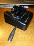
It looks like it should work, but I can not confirm if it is electrically identical to the one specified earlier in this thread. I used the Radio Shack one referenced in here, and it worked perfectly. I did not cut the end off the cable, but instead installed a matching 1/8" phone jack in the back of the charger shell. FWIW, the Radio Shack USB to Serial cable came with my scanner and is used to to program it so in no way did I want to modify the cable.

When I built mine, I was able to successfully use a regular Minitor IV charger and modify it so that it would either work as a programming cradle or as a standard pager charger. I did have to rape a second charger for parts, but in the end it worked exactly as intended. There was no indication from the outside that it had been modified except for the phono jack on the back side.
 

SCPD

QRT
Joined
Feb 24, 2001
Messages
0
Location
Virginia
Thank You Steve for all your help, after you explained some things to me, I have a better understanding to what did wrong & why they were needed. I just ordered my USB to TTL converter, but will take a little bit to receive it, but when it's done & hopefully working, I will let you know. THANK YOU AGAIN...George
 

cox402

Member
Joined
Apr 15, 2011
Messages
1
Pin Diagram Question

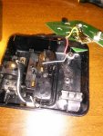
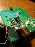
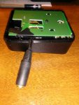
Here are the pics of the adapter base that I made. Crude but it works. The programming cable is for my Kenwood radios so I just needed to match the pins up.

Kevin

Can you share the pin diagram for the kenwood cable to the phone jack?
 

phillydjdan

Member
Joined
Jan 27, 2011
Messages
2,075
Here's my take on this:

I had a charging cradle that I don't use (I use AAA batteries instead), so I decided to reuse it as a programming cradle. I simply moved the 2 pins already in the base to the contacts that were present on the board. I then added a homebrew flexible contact using a paperclip, affixing it to the housing using an existing hole with a sheet rock anchor and a screw. I then soldered the headphone jack to the contacts and covered everything in electrical tape to prevent any shorting and presto! Works like a charm, and didn't cost me a dime!
 

Attachments

  • CAM00679.jpg
    CAM00679.jpg
    68.2 KB · Views: 1,138
  • CAM00681.jpg
    CAM00681.jpg
    59.1 KB · Views: 1,178
  • CAM00684.jpg
    CAM00684.jpg
    71.1 KB · Views: 1,353
  • CAM00685.jpg
    CAM00685.jpg
    71.4 KB · Views: 1,477

buildintechie

Member
Joined
Aug 11, 2007
Messages
6
I know this is an old thread, but I'm having a little difficulty.

I've built the programmer out of an extra 5 base, and have no problems with the Minitor Vs. We also have some IVs, and I built another programmer using a 4 base, and can read the IV fine. When I try to write to it I get an error. Thoughts? There isn't a USB delay function on the IV PPS.

thanks

~Jeff
 

firebal

Member
Premium Subscriber
Joined
Dec 28, 2011
Messages
242
Location
Baltimore, MD
It looks like it should work, but I can not confirm if it is electrically identical to the one specified earlier in this thread. I used the Radio Shack one referenced in here, and it worked perfectly. I did not cut the end off the cable, but instead installed a matching 1/8" phone jack in the back of the charger shell. FWIW, the Radio Shack USB to Serial cable came with my scanner and is used to to program it so in no way did I want to modify the cable.

When I built mine, I was able to successfully use a regular Minitor IV charger and modify it so that it would either work as a programming cradle or as a standard pager charger. I did have to rape a second charger for parts, but in the end it worked exactly as intended. There was no indication from the outside that it had been modified except for the phono jack on the back side.

Can you show how? With Pictures?
 

gilly1191

Newbie
Joined
Jan 28, 2015
Messages
2
Location
Rochelle,IL
help

Im Going to try to make this out of a phone jack.. im a little confused on how to connect the phone jack to the usb cable.. any help would be appreciated thanks
 
Status
Not open for further replies.
Top